这个例子展示了如何将地面真实数据与车道边界检测算法的结果进行比较。它还说明了如何使用这种比较来调整算法参数以获得最佳检测结果。
36.1 概述
地面真实数据通常以图像坐标提供,而边界则以车辆坐标系建模。比较两者涉及到坐标转换,因此在解释结果时需要格外小心。驾驶决策是基于车辆坐标系中的距离。因此,使用车辆坐标中的物理单位而不是像素坐标来表达和理解精度要求更为有用。
MonoCameraExample描述了单目摄像头传感器的内部结构和车道边界的建模过程。这个例子展示了如何根据人工验证的地面真实数据评估这些模型的准确性。在建立比较框架后,扩展该框架以微调边界检测算法的参数,以获得最佳性能。
36.2 加载和准备地面真实数据
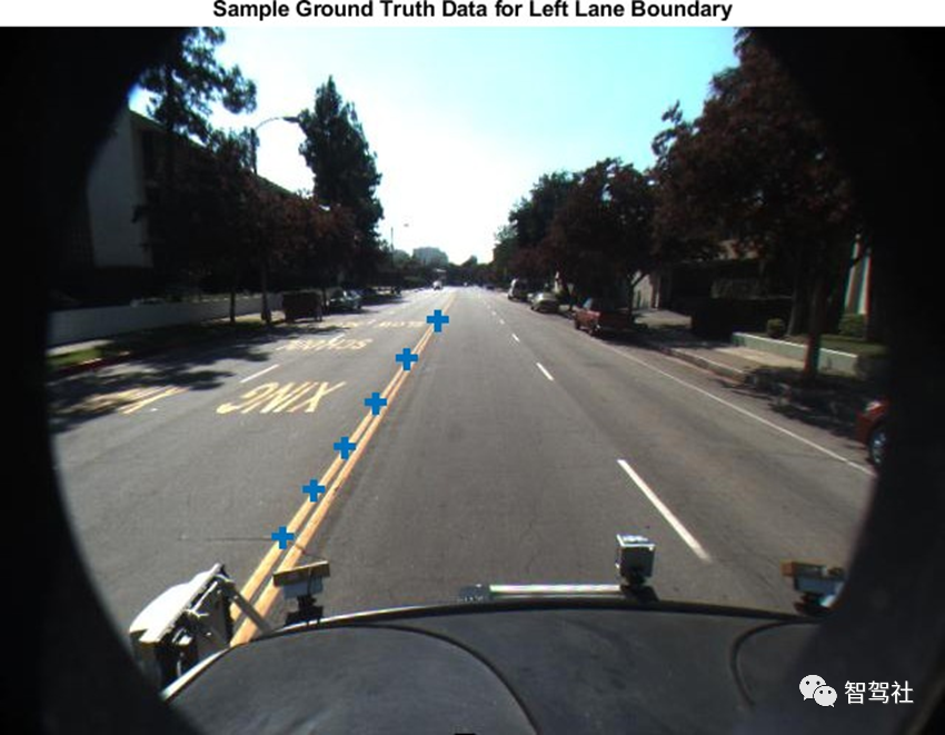
可以使用 Ground Truth Labeler 应用程序在视频中标记和标注车道边界。这些标注的车道边界被表示为沿感兴趣的边界放置的点集。在评估和微调自动车道边界检测算法时,拥有一组丰富的针对各种驾驶场景的手动注释车道边界是至关重要的。工具箱中提供了caltech_cordova1.avi视频文件的示例集。
加载预定义的左、右被控车道边界,以图像坐标指定。每个边界由一组M乘2的数字表示沿该边界的M个像素位置。每个视频帧至多有两个这样的集合,代表左车道和右车道。
loaded =load('caltech_cordova1_EgoBoundaries.mat');sensor =loaded.sensor; % Associated monoCamera objectgtImageBoundaryPoints= loaded.groundTruthData.EgoLaneBoundaries; % Showa sample of the ground truth at this frame indexframeInd =36; % Loadthe video frameframeTimeStamp= seconds(loaded.groundTruthData(frameInd,:).Time);videoReader= VideoReader(loaded.videoName);videoReader.CurrentTime= frameTimeStamp;frame =videoReader.readFrame(); %Obtain the left lane points for thisframeboundaryPoints= gtImageBoundaryPoints{frameInd};leftLanePoints= boundaryPoints{1}; figureimshow(frame)hold onplot(leftLanePoints(:,1),leftLanePoints(:,2),'+','MarkerSize',10,'LineWidth',4);title('Sample Ground TruthData for Left Lane Boundary');
将地面真实点从图像坐标转换为车辆坐标,以便与边界模型直接比较。
要执行此转换,请使用图像ToVehicle函数与关联的monoCamera对象来执行此转换。
gtVehicleBoundaryPoints = cell(numel(gtImageBoundaryPoints),1);for frameInd = 1:numel(gtImageBoundaryPoints) boundaryPoints = gtImageBoundaryPoints{frameInd}; if ~isempty(boundaryPoints) ptsInVehicle = cell(1, numel(boundaryPoints)); for cInd = 1:numel(boundaryPoints) ptsInVehicle{cInd} = imageToVehicle(sensor, boundaryPoints{cInd}); end gtVehicleBoundaryPoints{frameInd} = ptsInVehicle; endend
36.3 使用单目传感器建立车道边界模型
在样本视频上运行车道边界建模算法,获取测试数据进行对比。在这里,重用 "使用单目摄像头的视觉感知 "示例中介绍的helperMonoSensor模块。在处理视频的同时,还需要额外的一步来返回检测到的边界模型。这个逻辑被封装在本例最后定义的帮助函数 detectBoundaries 中。
monoSensor = helperMonoSensor(sensor);boundaries = detectBoundaries(loaded.videoName, monoSensor);
36.4 评估车道边界模型
使用evaluateLaneBoundaries函数来寻找与地面真值中那些边界相匹配的边界数量。只有当地面真值的所有点与相应的测试边界在指定的横向距离内时,地面真值才会被分配给测试边界。如果多个地面真值边界都满足这个标准,则选择最大横向距离最小的那个边界。其他的则标记为假阳性。
threshold = 0.25; % in vehicle coordinates (meters)[numMatches, numMisses, numFalsePositives, assignments] = ... evaluateLaneBoundaries(boundaries, gtVehicleBoundaryPoints, threshold);disp(['Number of matches: ', num2str(numMatches)]);disp(['Number of misses: ', num2str(numMisses)]);disp(['Number of false positives: ', num2str(numFalsePositives)]);Number of matches: 321Number of misses: 124Number of false positives: 25
可以使用这些原始计数来计算其他统计数字,如精确度、召回率和F1分数:
precision = numMatches/(numMatches+numFalsePositives);disp(['Precision: ', num2str(precision)]); recall = numMatches/(numMatches+numMisses);disp(['Sensitivity/Recall: ', num2str(recall)]); f1Score = 2*(precision*recall)/(precision+recall);disp(['F1 score: ', num2str(f1Score)]);Precision: 0.92775Sensitivity/Recall: 0.72135F1 score: 0.81163
36.5 使用鸟瞰图将结果可视化
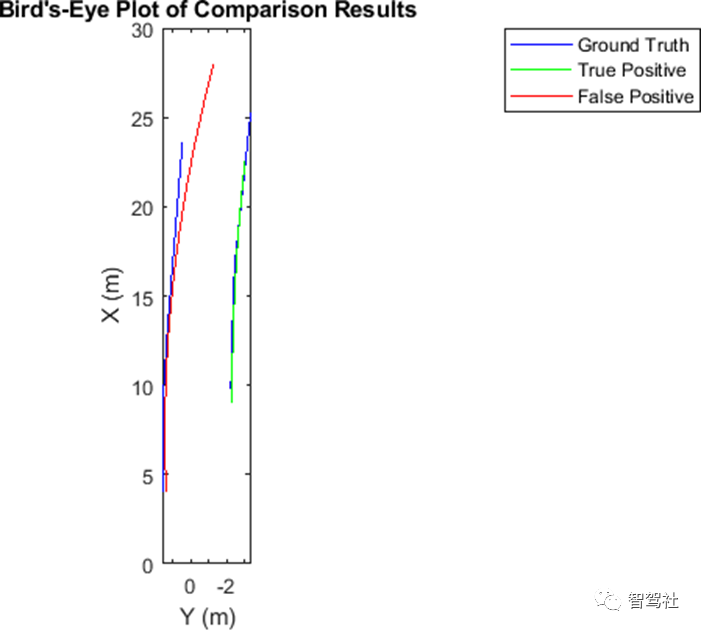
evaluateLaneBoundaries 还会返回地面真值和测试边界之间每一次成功匹配的赋值指数。这可以用来可视化检测边界和地面真值边界,以更好地了解失败模式。找到一个有一个匹配边界和一个假阳性的帧。每个帧的地真数据有两个边界。因此,一个候选帧将有两个赋值指数,其中一个为0表示假阳性。
hasMatch = cellfun(@(x)numel(x)==2, assignments);hasFalsePositive = cellfun(@(x)nnz(x)==1, assignments);frameInd = find(hasMatch&hasFalsePositive,1,'first');frameVehiclePoints = gtVehicleBoundaryPoints{frameInd};frameImagePoints = gtImageBoundaryPoints{frameInd};frameModels = boundaries{frameInd};使用evaluateLaneBoundaries的赋值输出,找到地面真值中匹配的模型(真阳性)和没有匹配的模型(假阳性)。matchedModels = frameModels(assignments{frameInd}~=0);fpModels = frameModels(assignments{frameInd}==0);设置鸟瞰图,并在鸟瞰图上可视化地真点和模型。bep = birdsEyePlot();gtPlotter = laneBoundaryPlotter(bep,'DisplayName','GroundTruth',... 'Color','blue');tpPlotter = laneBoundaryPlotter(bep,'DisplayName','True Positive',... 'Color','green');fpPlotter = laneBoundaryPlotter(bep,'DisplayName','False Positive',... 'Color','red'); plotLaneBoundary(gtPlotter, frameVehiclePoints);plotLaneBoundary(tpPlotter, matchedModels);plotLaneBoundary(fpPlotter, fpModels);title('Bird''s-Eye Plot of Comparison Results');
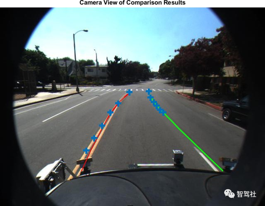
36.6 在摄像机和鸟瞰图中可视化视频结果为了更好地了解结果的背景,你还可以在视频上可视化地真点和边界模型。获取感兴趣的帧对应的帧。 videoReader = VideoReader(loaded.videoName);videoReader.CurrentTime = seconds(loaded.groundTruthData.Time(frameInd));frame = videoReader.readFrame();
将边界模型视为一条实线(不管传感器如何分类),以实现可视化。
fpModels.BoundaryType = 'Solid';matchedModels.BoundaryType = 'Solid';
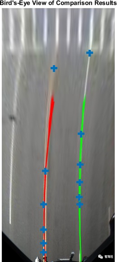
插入匹配的模型、假阳性和地面真点。此图有助于推断出,横道的存在对边界建模算法构成了挑战的情况.
xVehicle = 3:20;frame = insertLaneBoundary(frame, fpModels, sensor, xVehicle,'Color','Red');frame = insertLaneBoundary(frame, matchedModels, sensor, xVehicle,'Color','Green');figureha = axes;imshow(frame,'Parent', ha); % Combine the left and right boundary pointsboundaryPoints = [frameImagePoints{1};frameImagePoints{2}];hold onplot(ha, boundaryPoints(:,1), boundaryPoints(:,2),'+','MarkerSize',10,'LineWidth',4);title('Camera View of Comparison Results');
也可以在这个框架的鸟瞰图中直观地看到结果。birdsEyeImage= transformImage(monoSensor.BirdsEyeConfig,frame); xVehicle =3:20;birdsEyeImage= insertLaneBoundary(birdsEyeImage, fpModels, monoSensor.BirdsEyeConfig,xVehicle,'Color','Red');birdsEyeImage= insertLaneBoundary(birdsEyeImage, matchedModels, monoSensor.BirdsEyeConfig,xVehicle,'Color','Green'); %Combine the left and right boundarypointsptsInVehicle= [frameVehiclePoints{1};frameVehiclePoints{2}];gtPointsInBEV = vehicleToImage(monoSensor.BirdsEyeConfig,ptsInVehicle); figureimshow(birdsEyeImage);hold onplot(gtPointsInBEV(:,1),gtPointsInBEV(:,2),'+','MarkerSize', 10,'LineWidth',4);title('Bird''s-EyeView of Comparison Results');
36.7 调整边界模型参数
可以使用前面描述的评估框架来微调车道边界检测算法的参数,helperMonoSensor公开了三个控制车道查找算法结果的参数。
LaneSegmentationSensitivity- 控制 segmentLaneMarkerRidge 函数的灵敏度。该函数以二进制车道特征掩码的形式返回车道候选点。灵敏度值可以在0到1之间变化,默认值为0.25。增加这个数字会导致更多的车道候选点和更多的错误检测。
LaneXExtentThreshold- 指定车道的最小范围(长度)。它表示为检测到的车道长度与指定摄像机配置的最大车道长度的比率。默认值为 0.4。增加这个数字可以拒绝较短的车道边界。
LaneStthrengthThreshold- 指定接受检测到的车道边界的最小归一化强度。
LaneXExtentThreshold和 LaneStrengthThreshold 来自 parabolicLaneBoundary 对象的 XExtent 和 Strength 属性。这些属性是一个例子,说明如何在边界建模算法上放置额外的约束条件以获得可接受的结果。改变LaneStrengthThreshold的影响还有其他值得探讨的细微差别。典型的车道边界用实线或虚线标记。当与实线比较时,虚线具有较少的内联点,导致强度值较低。这使得设置一个通用的强度阈值具有挑战性。要检查该参数的影响,首先通过将LaneStrengthThreshold设置为0来生成所有边界,该设置确保它对输出没有影响。
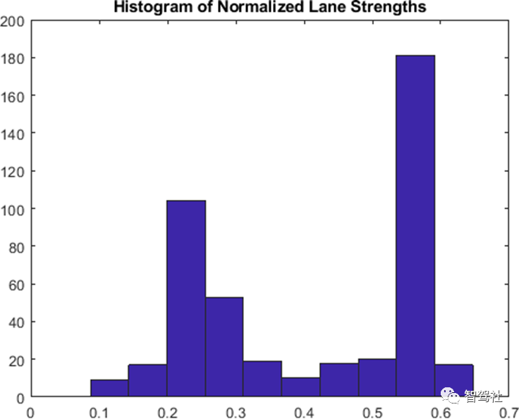
monoSensor.LaneStrengthThreshold= 0;boundaries = detectBoundaries('caltech_cordova1.avi',monoSensor); helperMonoSensor的 LaneStrengthThreshold 属性控制了每个抛物线车道边界模型的归一化强度参数。归一化系数 MaxLaneStrength 是运行于鸟眼图像全部范围的虚拟车道的强度。该值完全由 helperMonoSensor 的 birdsEyeView 配置决定。要评估LaneStrengthThreshold的影响,首先计算样本视频中所有检测到的边界的归一化车道强度的分布。注意存在两个明显的峰值,一个是归一化强度为0.3,一个是0.7。这两个峰值分别对应虚线和实线边界。从这个图中,您可以根据经验判断,为了确保检测到虚线车道边界,LaneStrengthThreshold应该低于0.3。
strengths =cellfun(@(b)[b.Strength], boundaries,'UniformOutput',false);strengths =[strengths{:}];normalizedStrengths= strengths/monoSensor.MaxLaneStrength;figure;hist(normalizedStrengths);title('Histogramof Normalized Lane Strengths');
可以使用对比框架进一步评估LaneStrengthThreshold参数对建模算法检测性能的影响。请注意,控制模型与地面真值之间最大物理距离的阈值与以前相同。这个值是由ADAS系统的精度要求决定的,通常不会改变。
threshold =.25;[~, ~, ~,assignments] = ... evaluateLaneBoundaries(boundaries, gtVehicleBoundaryPoints,threshold);
根据每个边界的归一化强度对其进行分类。分配信息有助于将每个边界分类为真阳性(匹配)或假阳性。LaneStrengthThreshold是一个 "最小 "阈值,因此在给定值时被分类为真阳性的边界将继续在所有较低的阈值中成为真阳性。
nMatch =zeros(1,100); % Normalized lanestrength is bucketed into 100 binsnFP = zeros(1,100); % ranging from 0.01 to1.00.for frameInd =1:numel(boundaries) frameBoundaries = boundaries{frameInd}; frameAssignment = assignments{frameInd}; for bInd =1:numel(frameBoundaries) normalizedStrength =frameBoundaries(bInd).Strength/monoSensor.MaxLaneStrength; strengthBucket = floor(normalizedStrength*100); if frameAssignment(bInd) % This boundary was matched with a ground truthboundary, % record as a truepositive for all values of strength above % its strength value. nMatch(1:strengthBucket) =nMatch(1:strengthBucket)+1; else % This is a falsepositive nFP(1:strengthBucket) =nFP(1:strengthBucket)+1; end endend
使用该信息来计算 "遗漏 "边界的数量,即算法在指定的LaneStrengthThreshold值下未能检测到的地面真实边界。并利用该信息,计算精度和召回指标。
gtTotal =sum(cellfun(@(x)numel(x),gtVehicleBoundaryPoints));nMiss = gtTotal - nMatch; precisionPlot= nMatch./(nMatch + nFP);recallPlot = nMatch./(nMatch + nMiss);
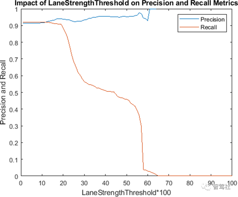
根据车道强度阈值参数的不同值绘制精度和召回指标。此图对于确定车道强度参数的最佳值非常有用。对于这个视频片段,为了最大限度地提高召回和精度指标,LaneStrengthThreshold应该在0.20 - 0.25的范围内。
figure;plot(precisionPlot);hold on;plot(recallPlot);xlabel('LaneStrengthThreshold*100');ylabel('Precisionand Recall');legend('Precision','Recall');title('Impact ofLaneStrengthThreshold on Precision and Recall Metrics');
36.7 支持函数
在视频中检测边界
detectBoundaries使用预先配置的helperMonoSensor对象来检测视频中的边界。
function boundaries = detectBoundaries(videoName, monoSensor)videoReader = VideoReader(videoName);hwb = waitbar(0,'Detecting and modeling boundaries in video...');closeBar = onCleanup(@()delete(hwb));frameInd = 0;boundaries = {};while hasFrame(videoReader) frameInd = frameInd+1; frame = readFrame(videoReader); sensorOut = processFrame(monoSensor, frame); % Save the boundary models boundaries{end+1} =... [sensorOut.leftEgoBoundary, sensorOut.rightEgoBoundary]; %#ok<AGROW> waitbar(frameInd/(videoReader.Duration*videoReader.FrameRate), hwb);endend
视频的像素标签的自动化就完成了。现在可以继续标记其他感兴趣的对象,保存会话,或导出本次标记运行的结果。
原文标题 : 基于MATLAB&SIMULINK开发自动驾驶系统第三十六讲根据地面实况数据评估车道边界检测情况


