这个例子展示了如何根据已知的地面真值评估车道边界检测的性能。在本例中,您将通过计算拟合度来描述每帧车道边界检测算法的性能。此测量方法可用于确定、可视化和理解底层算法中的故障模式。
37.1 概述
随着人们对基于视觉的自动驾驶问题解决方案的兴趣越来越大,能够评估和验证检测算法的准确性变得非常重要。对于那些具有多个参数的检测算法来说,验证准确性尤为重要,这些参数可以通过调整来实现满足预定义质量要求的结果。这个例子通过一个这样的工作流程,其中可以测量车道边界的准确性水平。该工作流有助于在每帧基础上精确确定这些算法中的故障模式,以及描述其整体性能。该工作流程还可以帮助直观、定量地了解算法的性能。然后,可以利用这种理解来调整算法以提高其性能。
37.2 加载地面真实数据
本例中使用的数据集是来自于车辆行驶在街道上的前装摄像头的视频文件。车道边界的地面真值已经用地面真值标示器应用在视频上手动标示,使用标示为 "LaneBoundary "的Line ROI。这段视频长8秒,也就是250帧。它有三个交叉路口,几辆车(停放和移动),以及车道边界(双线,单线和虚线)。要为自己的视频创建一个地面真值车道边界数据集,你可以使用地面真值标签器应用。
% Load MATfile with ground truth dataloaded =load('caltech_cordova1_laneAndVehicleGroundTruth.mat');
加载的结构包含三个字段:
groundTruthData,一个有两列的时间表, LaneBoundaries和Vehicles。LaneBoundaries包含被控车道边界(左、右)的地真点,用XY点组成的单元数组表示,形成一条多线。Vehicles包含摄像机视图中车辆的地面真点边界框,用M乘4的[x,y,width,height]数组表示。
sensor, 一个monoCamera对象,包含安装在车辆上的校准相机的属性。这个对象可以让你估计车辆与前方物体之间的实际距离。
videoName,一个字符数组,包含存储帧的视频的文件名。
从这个结构中的数据,通过使用VideoReader循环浏览帧来打开视频文件。VideoReader对象使用一个helperMonoSensor对象来检测视频帧中的车道和物体,使用sensor中存储的摄像头设置。存储在gtdata中的时间表变量持有地面真实数据。这个变量包含了以后用于分析的每帧数据。
%Create a VideoReader object to read frames of the video.videoName = loaded.videoName;fileReader= VideoReader(videoName); % Theground truth data is organized in a timetable.gtdata =loaded.groundTruthData; %Display the first few rows of the ground truth data.head(gtdata)ans = 8x2 timetable Time Vehicles LaneBoundaries ____________ ____________ ______________ 0 sec {6x4 double} {2x1 cell} 0.033333 sec {6x4 double} {2x1 cell} 0.066667 sec {6x4 double} {2x1 cell} 0.1 sec {6x4 double} {2x1 cell} 0.13333 sec {6x4 double} {2x1 cell} 0.16667 sec {6x4 double} {2x1 cell} 0.2 sec {6x4 double} {2x1 cell} 0.23333 sec {5x4 double} {2x1 cell}
gtdata时间表有两列Vehicle和LaneBoundaries。在每个时间戳上,Vehicles列持有一个M乘4的车辆边界框数组,LaneBoundaries列持有一个左、右车道边界点的双元素单元格数组。
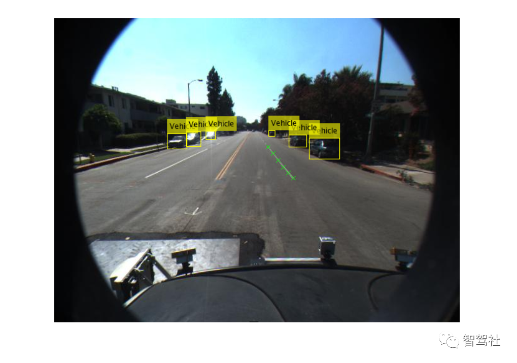
首先,可视化加载一个图像帧的地面真实数据。
% Readthe first frame of the video.frame =readFrame(fileReader); %Extract all lane points in the first frame.lanePoints= gtdata.LaneBoundaries{1}; %Extract vehicle bounding boxes in the first frame.vehicleBBox= gtdata.Vehicles{1}; %Superimpose the right lane points and vehicle bounding boxes.frame =insertMarker(frame, lanePoints{2}, 'X');frame =insertObjectAnnotation(frame, 'rectangle', vehicleBBox, 'Vehicle'); %Display ground truth data on the first frame.figureimshow(frame)
37.3 运行车道边界检测算法
使用视频帧和monoCamera参数,可以自动估计车道边界的位置。为了说明这一点,这里使用helperMonoSensor类的processFrame方法来检测车道边界(作为抛物线LaneBoundary对象)和车辆(作为[x,y,width,height]边界框矩阵)。在本例中,这是车道边界检测 "被测算法"。您可以使用相同的模式来评估自定义车道边界检测算法,其中processFrame被替换为自定义检测函数。车辆坐标中的地面真点也存储在gtdata时间表的LanesInVehicleCoord列中。这样一来,以后就可以在鸟瞰图显示中直观地看到它们了。首先,用传感器配置helperMonoSensor对象。helperMonoSensor类集合了运行车道边界检测算法所需的所有必要步骤。
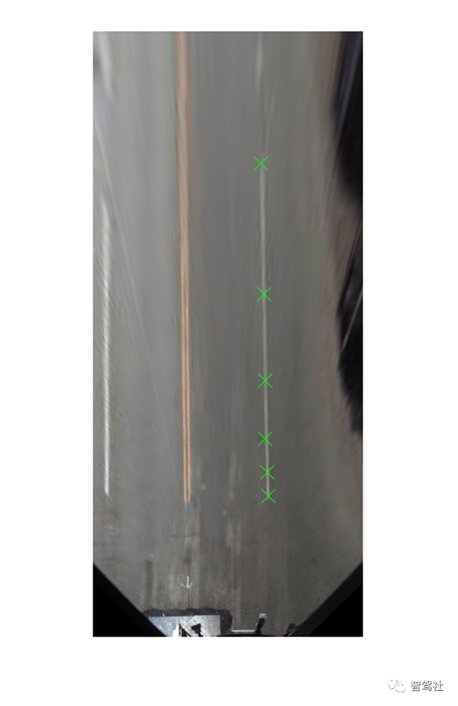
% Setup monoSensorHelper to process video.monoCameraSensor= loaded.sensor;monoSensorHelper= helperMonoSensor(monoCameraSensor); %Create new timetable with same Time vector for measurements.measurements= timetable(gtdata.Time); % Setup timetable columns for holding lane boundary and vehicle data.numFrames =floor(fileReader.FrameRate*fileReader.Duration);measurements.LaneBoundaries = cell(numFrames, 2);measurements.VehicleDetections= cell(numFrames, 1);gtdata.LanesInVehicleCoord = cell(numFrames, 2); %Rewind the video to t = 0, and create a frame index to hold current%frame.fileReader.CurrentTime= 0;frameIndex = 0; % Loopthrough the videoFile until there are no new frames.whilehasFrame(fileReader) frameIndex = frameIndex+1; frame = readFrame(fileReader); % Use the processFramemethod to compute detections. % This method can bereplaced with a custom lane detection method. detections = processFrame(monoSensorHelper,frame); % Store the estimatedlane boundaries and vehicle detections. measurements.LaneBoundaries{frameIndex} =[detections.leftEgoBoundary ... detections.rightEgoBoundary]; measurements.VehicleDetections{frameIndex}= detections.vehicleBoxes; % To facilitatecomparison, convert the ground truth lane points to the % vehicle coordinatesystem. gtPointsThisFrame =gtdata.LaneBoundaries{frameIndex}; vehiclePoints = cell(1,numel(gtPointsThisFrame)); for ii =1:numel(gtPointsThisFrame) vehiclePoints{ii} =imageToVehicle(monoCameraSensor, gtPointsThisFrame{ii}); end % Store ground truthpoints expressed in vehicle coordinates. gtdata.LanesInVehicleCoord{frameIndex} =vehiclePoints;end现在,已经用车道检测算法处理了视频,请验证地面真实点是否正确地转化为车辆坐标系。gtdata时间表的LanesInVehicleCoord列的第一个条目包含第一帧的车辆坐标。将这些地面真点绘制在鸟瞰图的第一帧上。
%Rewind video to t = 0.fileReader.CurrentTime= 0; % Readthe first frame of the video.frame =readFrame(fileReader);birdsEyeImage= transformImage(monoSensorHelper.BirdsEyeConfig, frame); %Extract right lane points for the first frame in Bird's-Eye View.firstFrameVehiclePoints= gtdata.LanesInVehicleCoord{1};pointsInBEV= vehicleToImage(monoSensorHelper.BirdsEyeConfig, firstFrameVehiclePoints{2}); %Superimpose points on the frame.birdsEyeImage= insertMarker(birdsEyeImage, pointsInBEV, 'X', 'Size', 6); %Display transformed points in Bird's-Eye View.figureimshow(birdsEyeImage)
37.4 测量检测误差
计算车道边界检测的误差是验证几个下游子系统性能的重要步骤。这些子系统包括车道偏离警告系统,它们依赖于车道检测子系统的准确性。
你可以通过测量拟合度的好坏来估计这个精度。有了地面真点和计算出的估计值,您现在可以对它们进行比较和可视化,以了解检测算法的性能如何。
拟合度可以在每帧或整个视频中进行测量。每帧统计数据提供了有关特定场景的详细信息,例如检测算法性能可能会发生变化的道路拐弯处的行为。全局统计提供了错过检测的车道数量的全局估计。
使用evaluateLaneBoundaries函数返回全局检测统计数据和一个分配数组。这个数组将估计的车道边界对象与相应的地面真点进行匹配。
evaluateLaneBoundaries函数中的阈值参数表示车辆坐标中的最大横向距离,以符合与估计的抛物线车道边界的匹配。
threshold =0.25; % in meters [numMatches,numMisses, numFalsePositives, assignments] = ... evaluateLaneBoundaries(measurements.LaneBoundaries, ... gtdata.LanesInVehicleCoord, ... threshold); disp(['Number ofmatches: ', num2str(numMatches)]);disp(['Number ofmisses: ', num2str(numMisses)]);disp(['Number offalse positives: ', num2str(numFalsePositives)]);Number ofmatches: 321Number ofmisses: 124Number offalse positives: 25
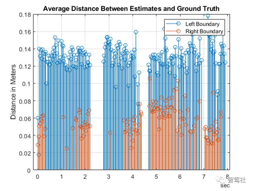
使用赋值数组,可以计算有用的每条车道指标,例如估计值与地面真点之间的平均横向距离。这些指标表明算法的性能如何。要计算平均距离度量,请使用本例末尾定义的辅助函数 helperComputeLaneStatistics。
averageDistance= helperComputeLaneStatistics(measurements.LaneBoundaries, ... gtdata.LanesInVehicleCoord, ... assignments,@mean); % Plotaverage distance between estimates and ground truth.figurestem(gtdata.Time,averageDistance)title('AverageDistance Between Estimates and Ground Truth')grid onylabel('Distancein Meters')legend('LeftBoundary','Right Boundary')
可视化并检视地面真值与你的算法之间的差异性。
现在已经对车道检测算法的准确性有了定量的了解。然而,仅根据上一节的图谱是不可能完全理解故障的。因此,查看视频并以每帧为基础将错误可视化对于识别特定的故障模式至关重要,可以通过完善算法来改进这些模式。
可以使用Ground Truth Labeler应用程序作为可视化工具来查看包含地面真值数据和估计车道边界的视频。driving.connect.Connector类提供了一个接口,用于将自定义的可视化工具附加到Ground Truth Labeler。
使用parabolicLaneBoundary数组和地面真值数据来计算估计点的车辆坐标位置。parabolicLaneBoundary数组定义了一条线,而地面真值数据则有道路上标记的离散点。助手GetCorrespondingPoints函数估计估计线上的点,这些点与车辆的Y轴距离一致。这个辅助函数在例子的最后定义。
现在,地面真值点和估计点被包含在一个新的时间表中,以便在地面真值标签器应用程序中可视化。然后,创建的groundTruth对象将被存储为一个MAT文件。
%Compute the estimated point locations using the monoCamera.[estVehiclePoints,estImagePoints] = helperGetCorrespondingPoints(monoCameraSensor, ... measurements.LaneBoundaries, ... gtdata.LanesInVehicleCoord, ... assignments); % Addestimated lanes to the measurements timetable.measurements.EstimatedLanes = estImagePoints;measurements.LanesInVehicleCoord= estVehiclePoints; %Create a new timetable with all the variables needed for visualization.names = {'LanePoints'; 'DetectedLanePoints'};types =labelType({'Line'; 'Line'});labelDefs =table(names, types, 'VariableNames', {'Name','Type'}); visualizeInFrame= timetable(gtdata.Time, ... gtdata.LaneBoundaries, ... measurements.EstimatedLanes, ... 'VariableNames', names); %Create groundTruth object.dataSource= groundTruthDataSource(videoName);dataToVisualize= groundTruth(dataSource, labelDefs, visualizeInFrame); % Saveall the results of the previous section in distanceData.mat in a% temporaryfolder.dataToLoad= [tempdir 'distanceData.mat'];save(dataToLoad,'monoSensorHelper', 'videoName', 'measurements', 'gtdata', 'averageDistance');
helperCustomUI类使用从MAT文件中加载的数据(如您刚刚创建的文件)创建绘图和鸟眼视图。Ground Truth Labeler 应用程序的 Connector 接口通过 helperUIConnector 类与 helperCustomUI 类进行交互,以同步视频与平均距离图和鸟眼视图。这种同步使您能够以分析和可视化的方式分析每帧结果。
按照这些步骤来可视化结果,如下面的图片所示。
进入保存distanceData.mat的临时目录,打开Ground Truth Labeler应用程序。然后启动Ground Truth Labeler应用程序,使用以下命令将连接器句柄指定为helperUIConnector。
>> origdir = pwd;>> cd(tempdir)>> groundTruthLabeler(dataSource,'ConnectorTargetHandle', @helperUIConnector)。
导入标签。在图像坐标中可视化地面真值车道标记和估计车道。从应用工具条中,点击导入标签。然后选择 "来自工作区 "选项,并将dataToVisualize地面真值加载到应用程序中。主应用程序窗口现在包含车道标记的注释。
现在可以浏览视频并检查错误。要返回到原始目录,可以键入。
>> cd(origdir)
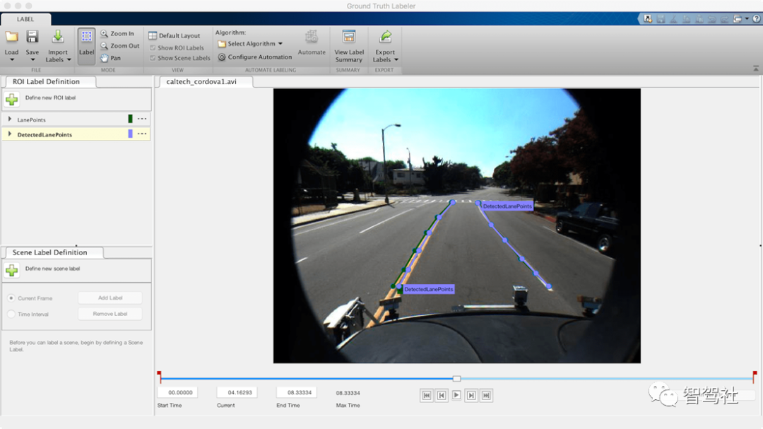
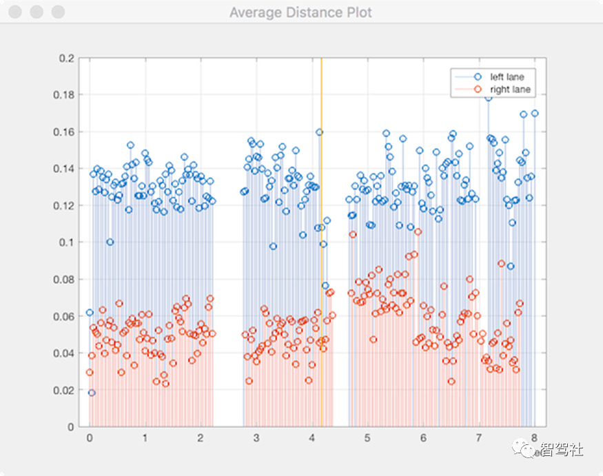
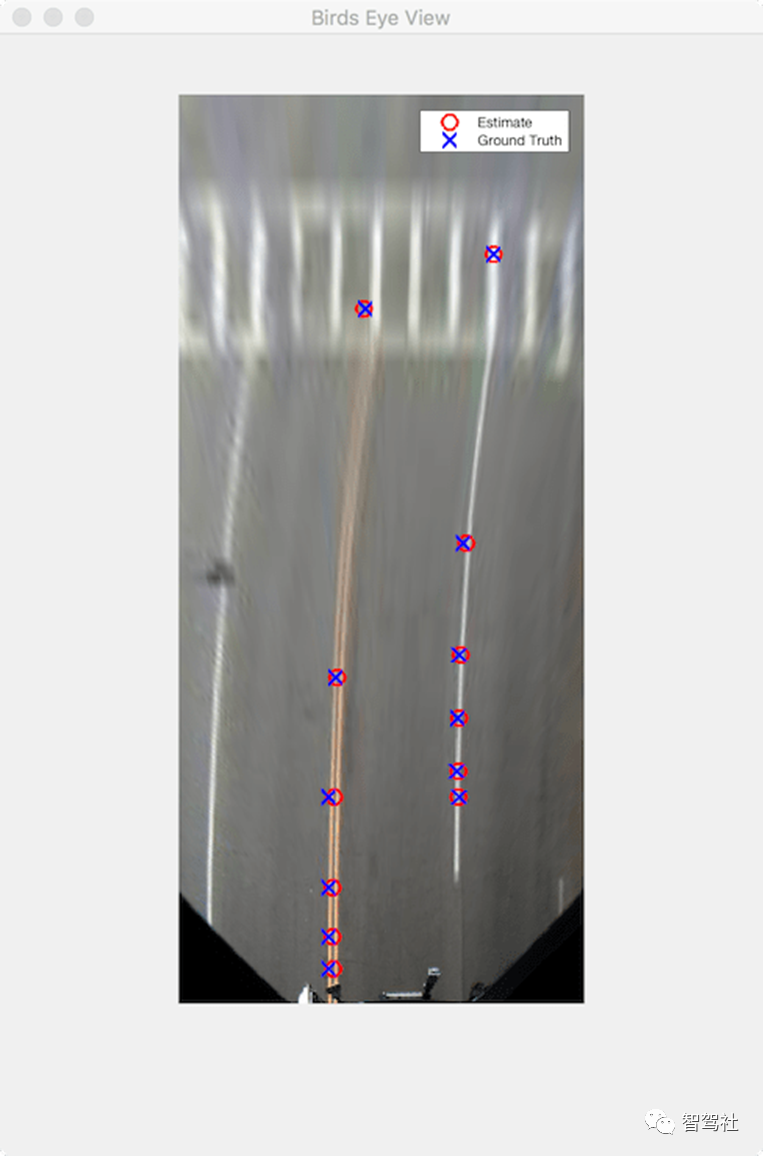
从这个可视化中,你可以对算法和地面真实数据的质量做出几个推断。
左侧车道的准确率一直比右侧车道的准确率差。在鸟瞰图显示中仔细观察,地面真实数据被标记为双线的外边界,而估计车道边界一般位于双线标记的中心。这说明左侧车道估计很可能比数字描绘的更准确,明确定义的地面真实数据集对此类观测至关重要。
2.3秒和4秒左右的检测间隙对应的是道路上的交叉口,而这些交叉口的前面都是人行道。这说明算法在有十字路口的情况下表现不佳。
6.8秒左右,当车辆接近第三个十字路口时,被控车道会分化成一条左侧专用车道和一条直行车道。在这里,算法也未能精确捕获到左侧车道,而地真数据也不包含任何信息的5帧。
37.5 总结结语
这个例子展示了如何使用Ground Truth Labeler应用程序测量车道边界检测算法的准确性并将其可视化。您可以将这一概念扩展到其他自定义算法,以简化这些工作流程,并扩展应用程序的功能以进行自定义测量。
37.6 支持功能helperComputeLaneStatistics
这个辅助函数计算车道边界检测与地面真实点相比的统计数据。它接收一个函数句柄,可以用来概括需要计算的统计量,包括@均值和@中值。
function stat =helperComputeLaneStatistics(estModels, gtPoints, assignments, fcnHandle) numFrames = length(estModels); % Make left and rightestimates NaN by default to represent lack of % data. stat = NaN*ones(numFrames, 2); for frameInd = 1:numFrames % Make left and rightestimates NaN by default. stat(frameInd, :) = NaN*ones(2, 1); for idx =1:length(estModels{frameInd}) % Ignore false positiveassignments. if assignments{frameInd}(idx)== 0 continue; end % The kth boundary inestModelInFrame is matched to kth % element indexed byassignments in gtPointsInFrame. thisModel =estModels{frameInd}(idx); thisGT = gtPoints{frameInd}{assignments{frameInd}(idx)}; thisGTModel =driving.internal.piecewiseLinearBoundary(thisGT); ifmean(thisGTModel.Points(:,2)) > 0 % left lane xPoints =thisGTModel.Points(:,1); yDist = zeros(size(xPoints)); for index = 1:numel(xPoints) gtYPoints =thisGTModel.computeBoundaryModel(xPoints(index)); testYPoints =thisModel.computeBoundaryModel(xPoints(index)); yDist(index) =abs(testYPoints-gtYPoints); end stat(frameInd, 1) =fcnHandle(yDist); else% right lane xPoints =thisGTModel.Points(:,1); yDist = zeros(size(xPoints)); for index = 1:numel(xPoints) gtYPoints =thisGTModel.computeBoundaryModel(xPoints(index)); testYPoints =thisModel.computeBoundaryModel(xPoints(index)); yDist(index) = abs(testYPoints-gtYPoints); end stat(frameInd, 2) =fcnHandle(yDist); end end endendhelperGetCorrespondingPoints(对应点)
该辅助功能在X轴位置创建与地面真实点相匹配的车辆和图像坐标点。
function[vehiclePoints, imagePoints] = helperGetCorrespondingPoints(monoCameraSensor,estModels, gtPoints, assignments) numFrames = length(estModels); imagePoints = cell(numFrames, 1); vehiclePoints = cell(numFrames, 1); for frameInd = 1:numFrames ifisempty(assignments{frameInd}) imagePointsInFrame = []; vehiclePointsInFrame = []; else estModelInFrame =estModels{frameInd}; gtPointsInFrame =gtPoints{frameInd}; imagePointsInFrame = cell(length(estModelInFrame),1); vehiclePointsInFrame =cell(length(estModelInFrame), 1); for idx =1:length(estModelInFrame) % Ignore false positiveassignments. if assignments{frameInd}(idx)== 0 imagePointsInFrame{idx} =[NaN NaN]; continue; end % The kth boundary inestModelInFrame is matched to kth % element indexed byassignments in gtPointsInFrame. thisModel =estModelInFrame(idx); thisGT =gtPointsInFrame{assignments{frameInd}(idx)}; xPoints = thisGT(:, 1); yPoints =thisModel.computeBoundaryModel(xPoints); vehiclePointsInFrame{idx} =[xPoints, yPoints]; imagePointsInFrame{idx} =vehicleToImage(monoCameraSensor, [xPoints yPoints]); end end vehiclePoints{frameInd} = vehiclePointsInFrame; imagePoints{frameInd} = imagePointsInFrame; % Make imagePoints []instead of {} to comply with groundTruth object. ifisempty(imagePoints{frameInd}) imagePoints{frameInd} = []; end ifisempty(vehiclePoints{frameInd}) vehiclePoints{frameInd} = []; end endend
原文标题 : 基于MATLAB&SIMULINK开发自动驾驶系统第三十七讲根据地面实况对车道边界检测进行评估和可视化


